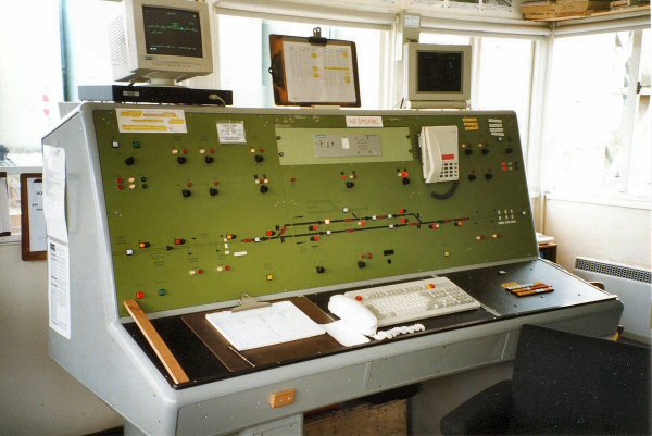
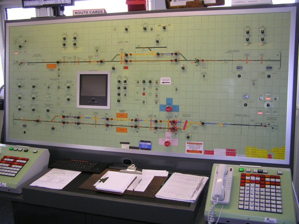
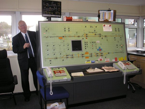
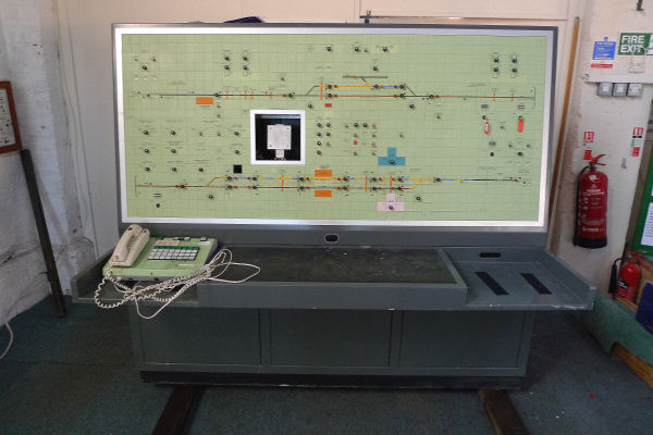
| Chard Junction Signalling Panel Project - Can you help? To go directly to latest updates please CLICK HERE This panel, including the crossing at Axminster, and Axminster Station was brought into use on 27th November 2009 after the doubling of the line through Axminster Station. Chard Junction Signalbox finally closed at 0115hrs on 10th March 2012. The panel was removed and taken to Yeovil Railway Centre. Previous History
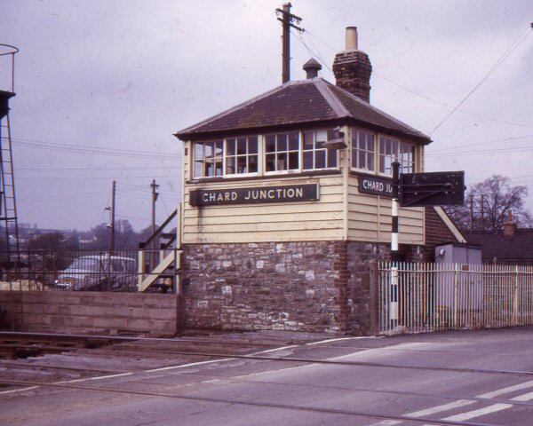
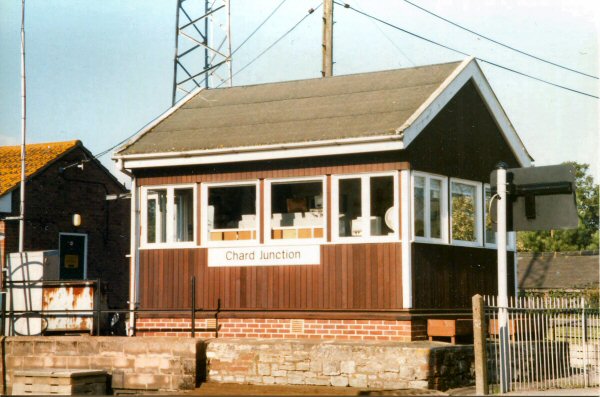
On 11 September 1982 a temporary signalbox and panel were brought into use on the opposite side of the line and the road, after which the old signalbox was demolished and a new structure built on the same site. (The diagram from the old signalbox could be seen in the Gauge Museum at Bishops Lydeard station on the West Somerset Railway, but is now not on display).
Chard Junction Signalling Panel (update July 2024) During 2023, operational limitations of the current housing was discovered, leading to a new a new electronics cabinet being collected and installed. The Chard Junction signal panel is progressing well thanks to the help of Ian who is able to help program the Axminster section of the panel using JMRI. 2024 has seen some much needed assistance in the form of three new volunteers helping to develop the panel, but more help is always welcomed. The next stage, while programming continues, is to reinstate the analogue system, this links the panel to a demonstration model to show how the system was used on the mainline. There is plenty more to be done with the museum space to gain many more interactive signalling related exhibits as time and funds allow. Chard Junction Signalling Panel (update January 2022) A few photos of various work being undertaken. A link between a demonstration 00 Gauge railway and the Signalling Panel is being created as well as wiring up more of the track circuits on the panel. 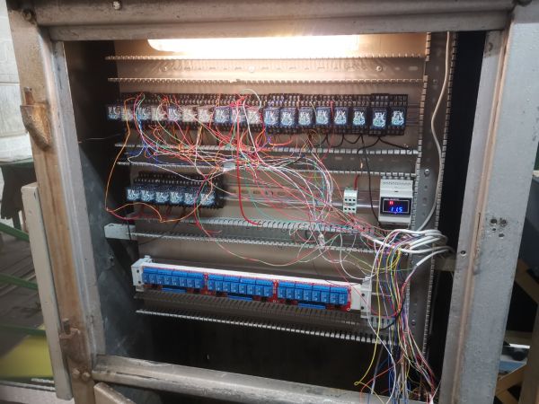 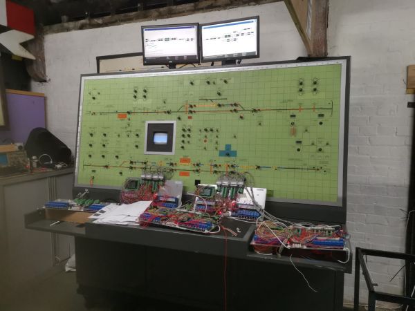 Chard Junction Signalling Panel (update January 2021) 2020 Signal Panel Report - Click Here Chard Junction Signalling Panel (update November 2019) 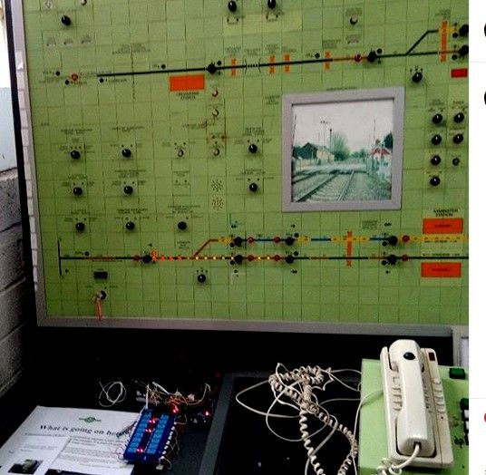 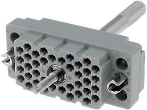 We now have a working simultaion of the lights which show when a train passes through Axminster East Junction. We are over half-way through connecting all eighteen 38-way connectors, and building the panels containing the connectors, relays and micro-computers that will eventually connect each switch and light to the central control computer. We are working with using JMRI on a control computer to simulate the track layout which will recognise when routes have been set, and deal wth the passage of trains throughout the complete routes from Yeovil Junction to Honiton. The first stage is to understand JMRI (a Java-based Model Railroad Interface) and to built a virtual copy of the tracks and the trains. We have started looking at how the JMRI simulation will connect with the microcomputers controlling each signal and reading each switch. We have started looking at how the Panel will communicate with the two nearest signal boxes, which were at Yeovil Junction and Honiton. We have acquired a buzzer and big brass push button to simulate the Honiton box, so that a train can be 'offered' from one box to the other, which simulates the way each signal box communicates with its neighbour. We are still looking for people with automated model railway experience (particularly JMRI), and others with in-depth Arduino programming experience. And of course we are looking for donations to the project, as we are having to buy the parts we cannot scrounge from friendly sources of computers, monitors, cable and connectors. Tony Reese, with many thanks to Roger Higgins, Will Gane and Peter Owen, and to the Swindon Panel Society at Didcot Railway Centre, who have been an inspiration for what we are attempting. Chard Signalling Panel.(Update 04 March 2019)  For Arduino Day 2019, we will be demonstrating how we use an Arduino to simulate the panel lights for a passing train. We shall also be displaying how we intend to link multiple Arduinos together to communicate with a central controlling PC. We would be excited to see anyone who knows anything about programming Arduino computers, or who would like to learn at the first Steam Day of the season on March 17th. Chard Junction Signalling Panel March 2019 One year on from looking at this panel and wondering what to do with it - we have begun working on it. We decided to keep the 18 38-way connectors, and have succeeded in wiring up the first one. All the lights connected to this connector are working and we have proved the concept of how to get all the others working. We have designed and prototyped the first of several sliding drawers which will house all the electronics. These will be modular and removeable so that we can work with them on a bench. A design for a power supply drawer has also been done - containing 240v, 24v, 5v and flashing power supplies. We have obtained a number of Arduino Mega micro-computers, which will act as internediary controls between a PC and the connectors. Much programming design and development work is still required, but we have a plan. March 16th was designated as 'Arduino Day' so we have set up a Facebook page, and link to the Arduino Day, to try to attract some Arduino enthusiasts. We are still looking for more helpers, and some hardware, but we are now a little clearer about what we want. Come and join us on a Sunday morning, for some fun and some design and development work (Update 28 May 2018) Work continues on trying to understand what it consists of and what we would need to make it into a simulation. Network Rail have kindly given us the complete wiring diagram, not only for the panel, but for much of the relay room, which stood (still stands) near where the signal box was. We are very fortunate to have the complete list of connectors and their connections (18 connectors each with 38 connection points). The table lists the function of each connection, written in something called 'the signaller's alphabet'. We have been given a table explaining this, and some help in working out how to read the diagram. We have set up one route/path from the signal at the eastern end of the Axminster loop into the up loop - this was used for most down services during the life of this panel. This can be switched on and off - we have some switches to simulate it manually, and a program running on an Arduino to do it as an automated simulation. That's one route - a few hundred more, and wiring up some of the accessory switches and we'll be there! We need more help, particularly cutting and connecting cables, and documenting and if anyone can help with supplying - - cables - connectors - a monitor - micro computers (we are using 2 Arduinos at the moment, but open to suggestions) Also - could someone take a video camera to Axminster crossing? We could do with a complete sequence of the gates closing, a tran passing and the gates opening again. In both directions, and preferably on both tracks. Without trespassing on NR property, and from the point of view of the NR camera. Earlier News The Next Steps - find a team of people who know about how signalling systems work and check out and document the panel. We will also need computer programmers and people used to working with electronics - Design a system to provide inputs and outputs - Design a simulation that will work with a given timetable - Design a system that will work with Network Rail inputs (the data stream that feeds Real Time Trains and Open Train Times If you are interested in this project or you know someone who might be, please get in touch with:- Tony Reese Yeovil Railway Centre, Yeovil Junction Station, Stoford, YEOVIL BA22 9UU tony.reese@mail.com 07967 947335 |
| BACK |